
Choosing the right Pneumatic Cylinder begins with the real machine, not a product photograph. Every application has different loads, speeds, strokes, mounting limits, and environmental pressures. A cylinder moving a light gripper behaves differently from one pushing a metal fixture through repeated cycles. The details matter.
Pneumatic automation specialist Peter Rohner offers a practical reminder: “Size the actuator for the task, not for appearance.” This principle reflects years of fluid-power engineering experience. Engineers should calculate the required force, then consider air pressure, friction, cushioning, rod strength, and duty cycle. A larger bore may deliver more force, but it can also consume more compressed air and increase operating costs. Bigger is not always better.
Look closely at the working environment. Dust, moisture, heat, cleaning chemicals, and side loads can quickly expose a weak selection. Stainless-steel components may suit washdown areas. Guided cylinders may handle alignment better than standard models. Adjustable cushioning can reduce the sharp impact heard at each stroke. That sound is a warning, sometimes.
This guide explains how to compare cylinder types, bore sizes, stroke lengths, mounting styles, and seal materials. It also considers speed control, energy efficiency, maintenance access, and safety-related design decisions. Some selections remain imperfect. Real machines change, and catalog calculations cannot predict every vibration or misalignment. Careful testing is still necessary. The right Pneumatic Cylinder should perform reliably today and leave enough practical tolerance for tomorrow.
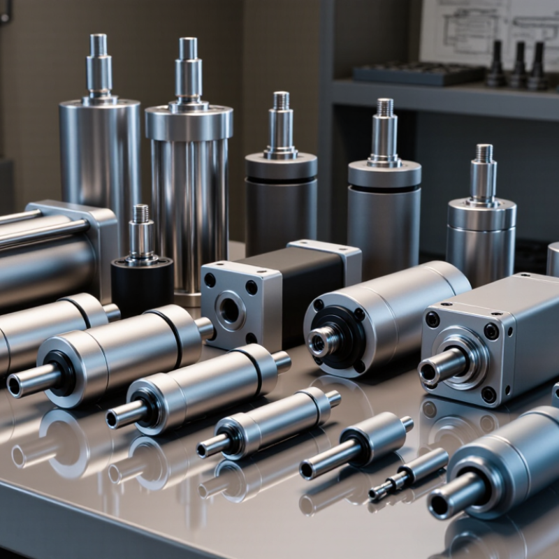
Choosing a pneumatic cylinder starts with its operating principle, not its catalog size. Compressed air enters a chamber and pushes a piston. The piston transfers force through a rod or carriage. Pressure, piston area, and friction determine usable thrust. A simple estimate is F = P × A, but real loads need a safety margin. Double-acting cylinders use air for both strokes. Single-acting cylinders use a spring for return. They suit lighter, simpler movements.
Rodless cylinders move a carriage along the barrel. They save space when long strokes would bend a rod. Rotary actuators convert air pressure into angular motion. During commissioning, I check the first cycle at low speed. Start gently. A load may jerk if the valve opens too quickly. Flow controls and adjustable cushions help manage that movement. Listen carefully. Hissing often reveals leakage or a damaged seal.
Choosing correctly means matching cylinder type to load, stroke, speed, mounting, and environment. Dust, moisture, and washdown conditions can change material and sealing requirements. Dimensions should also match the relevant pneumatic cylinder standard. A magnetic sensor may confirm piston position, but it cannot fix poor alignment. Misalignment creates side loads, uneven wear, and early failure. I inspect the rod surface and fittings after repeated cycles. This small check is easy to skip. Some earlier selections proved too optimistic. A larger bore is not automatically better. It can increase air use, impact, and operating cost.
How to Choose the Right Pneumatic Cylinder?
Defining load, force, speed, and stroke requirements starts with the actual motion. A 100-kilogram vertical load needs more than 981 newtons to lift. Add friction, acceleration, tooling weight, and a safety margin. At 6 bar, a 50-millimeter bore produces about 1,178 newtons theoretically. Real output is lower. Rod friction matters.
Speed depends on airflow, not pressure alone. A cylinder moving 300 millimeters in one second needs a different valve and tube size than one completing the stroke in four seconds. Specify extension and retraction speeds separately. Include stopping distance, cushioning, and cycle frequency. A short stroke can still create severe impact.
The U.S. Department of Energy’s Improving Compressed Air System Performance sourcebook reports that compressed-air systems can consume about 10% of industrial electricity. It also notes that leaks may waste 20–30% of compressor output. That makes correct sizing an energy decision, not only a mechanical one. Oversizing feels safe, but it can increase air consumption and impact force. I have seen calculations miss the rod load. Recheck the worst position. Do not ignore side loading, temperature, mounting alignment, or pressure loss between the regulator and cylinder. Specification sheets are useful, but measured machine behavior should challenge them.
Defining load, force, speed, and stroke requirements starts with matching the cylinder bore to the required force at the available air pressure.
The chart shows the theoretical extension force of common cylinder bore sizes at 6 bar pressure. Force is calculated using F = P × A, where piston area is based on the bore diameter. Actual available force will be lower because of friction, pressure losses, and the required safety margin. Select the stroke for the required travel distance and verify the air-flow capacity to achieve the target speed.
Choosing the Right Pneumatic Cylinder
Bore size controls the cylinder’s available force. Estimate the required load before selecting a model. At 6 bar, a 50 mm bore produces about 1,178 N theoretically. Real output is lower after friction and pressure losses. Add a sensible safety margin, but avoid oversized cylinders. They consume more air and may create harsh motion. Stroke length should match the working distance, with a small allowance for adjustment.
The rod must resist the load without bending. Longer rods need extra attention, especially during horizontal movement. Side loading can damage seals and shorten service life. Use external guides when the load does not travel perfectly straight. Choose a threaded rod end that fits the clevis or linkage. Mounting style also matters. A fixed mount suits aligned motion, while a pivoting mount tolerates small changes in angle. Check the available space around ports, fasteners, and the retracting rod.
Material selection depends on the environment. Aluminum keeps the cylinder light, while stainless steel handles moisture and frequent cleaning better. Seal materials must suit the air quality, temperature, and any chemical exposure. Dry, filtered air is essential for consistent operation. I once treated mounting as a minor detail. It was not. A slightly misaligned bracket caused uneven wear and noisy movement. Recheck alignment under the actual load, not only on the workbench.
| Selection Dimension | Recommended Selection Method | Typical Options or Reference Data | Important Design Considerations |
|---|---|---|---|
| 1. Bore Selection and Force Capacity | |||
| Required cylinder force | Calculate the theoretical force from the working pressure and piston area, then apply a practical efficiency factor. |
Extension force:
F = P × πD² / 4 Retraction force: F = P × (πD² / 4 − πd² / 4) |
Use approximately 80–90% of theoretical force for preliminary sizing to allow for seal friction, pressure losses, alignment errors, and acceleration. |
| Working pressure | Choose a cylinder rated for the actual operating pressure and confirm the maximum allowable pressure in the technical specification. | Common operating range: approximately 4–7 bar (0.4–0.7 MPa). The reference force data below is calculated at 6 bar. | Do not size the cylinder only for the compressor’s maximum pressure. Consider pressure fluctuations and the pressure available at the cylinder port. |
| Small bore | Use when the load is light and compact size, low air consumption, and fast response are priorities. | Typical bore range: 12–25 mm. | Verify that the available force is sufficient after accounting for friction and the required safety margin. |
| Medium bore | Use for general automation, clamping, pushing, indexing, and material handling. | Typical bore range: 32–63 mm. | This range provides a practical balance between force, cylinder size, air consumption, and cost. |
| Large bore | Use for heavy loads or applications requiring high pushing and pulling forces. | Typical bore range: 80–125 mm or larger. | Check mounting rigidity, frame strength, compressed-air capacity, cushioning, and the increased moving mass. |
| Reference Force Data at 6 bar Working Pressure | |||
| Bore Diameter | Typical Rod Diameter | Effective Piston Area | Theoretical Extension / Retraction Force |
| 16 mm | 6 mm | 201 mm² / 173 mm² | Extension: 121 N Retraction: 104 N |
| 20 mm | 8 mm | 314 mm² / 264 mm² | Extension: 188 N Retraction: 158 N |
| 25 mm | 10 mm | 491 mm² / 412 mm² | Extension: 295 N Retraction: 247 N |
| 32 mm | 12 mm | 804 mm² / 691 mm² | Extension: 483 N Retraction: 415 N |
| 40 mm | 16 mm | 1,257 mm² / 1,056 mm² | Extension: 754 N Retraction: 633 N |
| 50 mm | 20 mm | 1,963 mm² / 1,649 mm² | Extension: 1,178 N Retraction: 989 N |
| 63 mm | 25 mm | 3,117 mm² / 2,626 mm² | Extension: 1,870 N Retraction: 1,576 N |
| 80 mm | 25 mm | 5,027 mm² / 4,536 mm² | Extension: 3,016 N Retraction: 2,722 N |
| 100 mm | 32 mm | 7,854 mm² / 7,050 mm² | Extension: 4,712 N Retraction: 4,230 N |
| 2. Rod Selection | |||
| Rod diameter | Select the rod diameter according to compressive load, unsupported length, stroke, and mounting alignment. | Common rod-to-bore combinations include 20/8 mm, 25/10 mm, 32/12 mm, 40/16 mm, 50/20 mm, and 63/25 mm. | A larger rod improves resistance to bending and buckling but reduces retraction force and increases cylinder mass. |
| Stroke length | Select the shortest stroke that completes the required movement without mechanical overtravel. | Typical automation strokes: 25–500 mm. Longer strokes are available when properly guided. | Long strokes increase buckling risk, rod deflection, vibration, and air consumption. Use an external guide for long or side-loaded applications. |
| Rod loading | Keep the cylinder rod primarily in axial tension or compression. | Use a guide rail, slide, or guided cylinder when the load creates side force or torque. | Side loading accelerates rod seal and bearing wear and can cause premature failure even when the calculated force is acceptable. |
| Rod end connection | Match the connection to the load movement and required adjustment. | Common choices: male thread, female thread, clevis, rod eye, spherical rod end, or adjustable joint. | Use a self-aligning connection where angular movement or minor misalignment is unavoidable. |
| 3. Mounting Selection | |||
| Fixed flange mounting | Choose for rigid, accurately aligned installations where the load remains in line with the cylinder axis. | Front or rear flange mounting. | Provides strong axial support but tolerates little angular misalignment. |
| Foot mounting | Choose when the cylinder is installed on a flat machine surface and the body must remain fixed. | Side or bottom mounting feet. | Use accurate alignment and avoid transferring bending moments into the rod. |
| Trunnion mounting | Choose when the cylinder must pivot around a fixed axis during operation. | Front, rear, or intermediate trunnion. | Suitable for angular movement, but the pivot structure must be strong enough to withstand the applied moment. |
| Clevis or pivot mounting | Choose for swinging mechanisms, hinged tooling, and applications requiring angular movement. | Rear clevis, front clevis, or pivot pin mounting. | Use a pivot pin with suitable bearing surfaces and ensure the cylinder is not exposed to unintended side loads. |
| Guided cylinder mounting | Choose when the cylinder must handle limited lateral force or prevent rotation of the load. | Integrated guide rods, guide blocks, or external linear guides. | Guided designs improve load control but may have higher friction and a larger installation envelope. |
| 4. Material and Environmental Selection | |||
| Standard indoor automation | Use conventional aluminum or coated steel construction with standard elastomer seals. | Suitable for clean, dry factory environments at moderate temperatures. | Provide clean, filtered, and adequately lubricated or non-lubricated compressed air according to the seal and cylinder specification. |
| Corrosive or washdown environment | Use corrosion-resistant body, rod, fasteners, and fittings. | Stainless steel or corrosion-resistant surface treatments; seals selected for water and cleaning-agent exposure. | Confirm chemical compatibility, washdown pressure, temperature, and protection of switches and connectors. |
| High-temperature environment | Select seals, grease, and materials rated above the continuous operating temperature. | High-temperature elastomers may be required for temperatures above approximately 80°C. | Check both continuous and peak temperature. Heat can reduce seal life and alter friction characteristics. |
| Low-temperature environment | Select seals and lubricants that remain flexible at the minimum ambient temperature. | Low-temperature seal compounds and lubricants may be required below approximately 0°C. | Moisture in compressed air can freeze and block valves or ports; use effective air drying and drainage. |
| Food, pharmaceutical, or hygienic service | Choose materials and lubricants suitable for the applicable hygiene requirements. | Stainless steel construction, smooth surfaces, and food-compatible lubricants where required. | Verify the specific cleaning process, chemical exposure, certification requirements, and hygienic design criteria. |
| Dusty or abrasive environment | Use protective rod scrapers and suitable seals. | Enhanced wipers, bellows, shields, or external rod protection. | Prevent abrasive particles from reaching the rod seal and bearing. Inspect the scraper regularly. |
| 5. Speed, Cushioning, and Control | |||
| Operating speed | Size the valve, tubing, and flow controls together with the cylinder. | Typical general-purpose cylinder speeds: approximately 50–500 mm/s, depending on bore, stroke, load, and circuit design. | Actual speed depends on airflow, pressure, load, exhaust restriction, tubing length, and valve capacity. |
| End-of-stroke cushioning | Use adjustable pneumatic cushioning for medium or high-speed movement and heavier loads. | Fixed cushion, adjustable cushion, external shock absorber, or elastomer stop. | Cushioning reduces impact, noise, vibration, and mechanical stress. It must be adjusted during commissioning. |
| Position sensing | Add sensors when the control system must confirm extended, retracted, or intermediate positions. | Magnetic reed or solid-state sensors mounted in the cylinder sensor groove. | Confirm sensor switching distance, voltage, current, cable routing, and resistance to the operating environment. |
| Load holding | Do not rely on a standard pneumatic cylinder alone to safely hold a suspended or hazardous load. | Mechanical rod lock, counterbalance, pilot-operated check valve, or independent mechanical support. | Use a risk-assessed safety method because compressed air is compressible and pressure can be lost unexpectedly. |
| 6. Final Specification Checklist | |||
| Required specification | Define bore, rod diameter, stroke, operating pressure, speed, mounting style, rod-end connection, sensors, cushioning, port size, and material. | Also specify air quality, ambient temperature, duty cycle, installation orientation, environmental exposure, and required service life. | |
| Practical safety margin | Select a cylinder with sufficient capacity beyond the calculated load rather than operating continuously at its theoretical limit. | Recheck force, buckling, mounting strength, air consumption, impact energy, and emergency-stop behavior before final approval. | |
Choosing a pneumatic cylinder starts with the air available at the machine. Catalog force is not working force. Pressure drops, dirty filters, and undersized tubing reduce it quickly. The U.S. Department of Energy reports that compressed air can consume about 10% of industrial electricity. Its industry sourcebook also estimates that leaks may waste 20–30% of compressor output. Measure pressure at the cylinder inlet. Do not size from compressor nameplate pressure.
Controls must match the motion, not merely start it. Use a regulator, flow controls, and correctly rated valves. Meter-out flow often gives smoother extension and limits load runaway. Check response time, cushioning, and sensor placement under the real load.
ISO 4414 stresses safe pneumatic design, including controlled energy isolation and predictable movement. Small errors matter. An aggressive pressure setting can hide poor sizing while increasing energy use.
Environmental conditions change the selection. ISO 8573-1 classifies compressed-air purity by particles, water, and oil, helping engineers specify filtration more precisely. At washdown stations, moisture-resistant materials and protected sensors deserve attention. In dusty areas, exposed rod seals may wear faster than expected. Temperature also affects seal behavior and lubrication.
A calculation can look perfect and still fail after three shifts. I have seen teams adjust flow controls repeatedly when the real problem was wet air and a restricted filter. Test the complete assembly, not just the cylinder.
Checking compatibility, safety, maintenance, and service life begins with the application, not the catalogue. Confirm the required force, stroke, speed, mounting position, air pressure, and operating temperature. A cylinder may fit mechanically but still perform poorly. Check the rod load and side force carefully. Misalignment can damage seals, increase friction, and shorten service life.
Safety needs equal attention. ISO 4414 provides safety principles for pneumatic systems, including controlled exhaust and protection against unexpected movement. Install regulators, lockout provisions, and suitable cushioning where motion stops abruptly. The U.S. Department of Energy reports that compressed air can represent about 10% of industrial electricity use. It also estimates that leaks may waste 20–30% of compressor output. That waste raises operating costs and can reduce cylinder response. I still see teams selecting oversized cylinders for comfort. It works, but it is not efficient.
Tips: Measure pressure at the cylinder, not only at the compressor.
Inspect rod alignment during installation. Listen for hissing near fittings. Record cycle counts and seal changes.
Clean the air supply, and replace filters on schedule. Follow ISO 8573 air-quality guidance when contamination threatens seals. Service intervals should reflect duty cycles, dust, moisture, and temperature. A fixed calendar is convenient, but sometimes wrong. Review the data after the first month.
A larger bore produces more force. At 6 bar, a 50 mm bore produces about 1,178 N theoretically. Actual output is lower because of friction and pressure losses. Add a sensible safety margin, but avoid excessive sizing.
Match the stroke to the required working distance. Add a small allowance for adjustment. A stroke that is too short may limit movement. A much longer stroke can waste space and increase mechanical risk.
Check the rod load, length, and movement direction. Long rods need extra support during horizontal travel. Avoid side loading whenever possible. Use external guides when the load does not move straight. Alignment matters more than expected.
Use a fixed mount for accurately aligned motion. Choose a pivoting mount when the angle changes slightly. Check the space around ports, fasteners, and the retracting rod. A small bracket error can cause noise and uneven wear.
Aluminum keeps the cylinder light. Moisture-resistant metal suits wet areas and frequent cleaning. Seal materials must match temperature, air quality, and chemical exposure. Dust can wear exposed rod seals quickly. Washdown areas need extra protection.
Compressor pressure does not equal working pressure. Restricted tubing, dirty filters, and leaks reduce available force. Measure pressure beside the cylinder during operation. Compressed air can consume significant electrical energy. Do not trust the nameplate alone.
Use a regulator, flow controls, and correctly rated valves. Meter-out flow often improves extension control. It can also reduce sudden load movement. Check cushioning, response time, and sensor position under the real load. Aggressive pressure settings may hide poor sizing.
Use dry, filtered air and replace filters on schedule. Listen for hissing around fittings. Inspect rod alignment during installation and operation. Record cycle counts and seal replacements. Review performance after the first month. A fixed service calendar may be wrong.
Choosing the right Pneumatic Cylinder begins with understanding how pneumatic systems convert compressed air into linear motion and how different cylinder types suit different applications. Start by defining the required load, operating force, movement speed, and stroke length. These factors help determine the suitable bore size and prevent problems such as insufficient power, unstable motion, or excessive air consumption.
Next, consider the cylinder rod, mounting arrangement, construction materials, and available installation space. The air supply must provide adequate pressure and flow, while valves, regulators, sensors, and control methods should support accurate and reliable operation. Environmental conditions, including dust, moisture, temperature, and exposure to chemicals, also influence material and protection choices. Finally, check system compatibility, safety requirements, maintenance access, sealing performance, and expected service life. A careful evaluation of these factors improves efficiency, reduces downtime, and ensures the selected cylinder performs safely and consistently throughout its working cycle.
